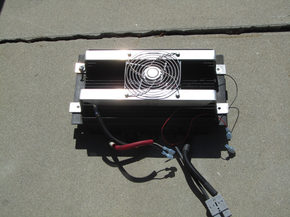
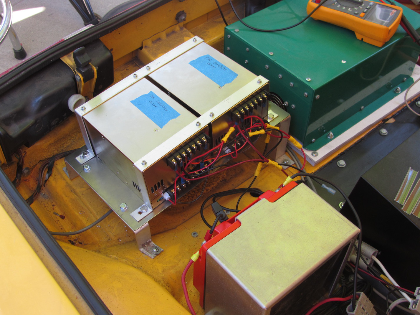
The old DC-DC converter was only producing 12.5v – not adequate for a normal charging system. After asking around, I ended up buying 2 Meanwell PSP-600-13.5 converters. These are great little boxes, in that they are designed to work in parallel. This also means that with two boxes, I now have 1200 watts of power to drive whatever I want – such as a new stereo.
Well, the old potbox was severely misbehaving, so I replaced it with a Curtis FP-6. Very solid, very nice. Well, it’s kinda big. But solid.
So, I pulled out the old gas pedal, and tried placing it on the floor. It sorta worked, but quite awkward to use. So I took out the old floorboard behind the gas pedal, made a new one I could mount the pedal to, and it is now quite usable. Especially when the carpet covers the wire and box.
It took a while, but I now have an embedded computer listening to the current going in and out of the battery. It is able to calculate the state of charge (SOC) of the pack, and display that value on a LCD screen. Simple enough, right? Just took time and shaking rust off some very old skills (wire-wrapping and soldering). In order to save the life of the auxillary battery, I have two power sources going into the computer. The battery directly powers the computer, and the keyed +12v drives the display. I’ll get some photos up later.
Ok, so the cooling system is all in place now – no leaks. I’ve got the pump hooked up to run whenever the key is on. Makes a small gurgle noise, so there is still some air in the system.
Hints: when installing new hoses, stretch the new hose where it will go over the barbs – makes life a LOT easier for the installer. Also, make sure the fittings are snug – otherwise, while the hose might be water-tight, the fitting could leak.
I was hoping to bring the car off the jackstands this weekend, but with the rain coming through, it is not very likely. Really don’t want to mix rain and electrical parts – especially since I haven’t re-installed the rear trunk lid.
Ok, the adaptor is complete, and ready to install. We’ve made a few attempts to put it in, but had a problem with the spacing around the clutch. This has been resolved by allowing the pressure plate to move back 0.2″. During the wait, I’ve rewired the relays, added in a pump and resevoir, and a third brake light. Hope to have the motor and transmission installed on Sunday.
The brake light is a strip of weatherproof side-facing LEDs from www.superbrightleds.com. The wires are hidden behind the chrome.
Since both the motor and the controller use liquid cooling, I had to add in a pump and reservoir. I’ll be running coolant lines from the pump to the controller to the motor to the radiators and back.
The new motor is heavy – 98kg! (216lb). So we have to use this hoist to get the motor and transmission into the car.
Motor hanging on a chain
The new motor is significantly larger than the old one. The gap between the new motor and the battery rack is about 6mm (1/4″).
Over the weekend I added some isolation to the charger and removed the ground connections, so the charger is completely floating now (relative to ground). This was done by putting some ABS plastic under the charger, and trimming off the ground wires that attach to the charger.
I also replaced the BMS master board, as the feedback from the charger might have damaged it. Not sure what did damage the BMS, but it is working now. I also had to turn the voltage down on the charger a bit – I suspect the voltage adjust knob is moving on its own.
The new BMS (minibms from Clean Auto LLC) was actually easy to install and understand. Only one minor complaint – the high-voltage alarm turns on if one of the cells triggers an alert – can be annoying to my neighbor as the car is parked next to his bedroom. I’ll add a relay to cut off the audible alarm.
So picture time. Here are the before pictures.
Front Trunk with old BMSRear pack with old BMS
Rear trunk with the old BMS and wiring
And here are the after pictures. Much nicer, no?
Front batteries with new BMSRear pack with new BMSNew BMS in rear trunkBattery Low/Fault light
The light is a repurposed CAT warning light – I’ll be adding a label to it later. Note that there is also a high-low tone buzzer just under the dash.
As promised, a picture of the crimper (got it from KTA). WONDERFUL tool. I wish I had it when I started.
Wonderful Crimper
I also installed two ammeters – one for the battery and one for the DC-DC converter. This shows me that both are working as promised, so my right-turn indicator problem is due to the older car wiring.
Battery and DC-DC Ammeters
I’ve been busy – this is a circuit that will drive the porsche 914 gas gauge from a 0-5v signal (from the BMS). I spent a few hours getting the resistors dialed in, but it works on the breadboard – now I just need to solder up a circuit board to do the same thing.
Ok, sorry for the delay. Over Thanksgiving weekend, with the aid of my brother-in-law, the new cables were installed. MUCH better on the ground fault problem. I also got to move the power cables to the right-side of the car – away from the communication cables.
So I found a VERY cheap way to solve the GFCI tripping problem – a $0.25 “cheater” plug. Yeah, it’s not elegant, but it solves the problem of the charger tripping the GFCI all the time. I’ll keep looking into why the charger behaves the way it does.
I’ll post pix later of the new cables and the new crimper.
I’ve gotten the computer installed and working. It does some very simple processing, that (to be honest) should have been handled by the motor controller.
The embedded computer measures the outside temperature of the motor, and then turns the motor fan on or off, and changes the power level of the motor controller.
Simple stuff, really. I’m sure *someone* could have done it entirely in hardware, but being a computer programmer from years back, this was a better way for me to go.
I’ve replaced all but the headlights with LEDs and seen a dramatic decrease in current during their usage. What was interesting is that I did not have to replace the blinker relay (apparently you need to on newer cars). I got the LEDs from www.superbrightleds.com.
I’ve also made regen a normal part of driving, so I’ll need to put back the circuit that lights up the brake lights when regen is active. The reason for this is to make shifting easier – when regen is active the motor quickly drops from high RPMs to almost zero within a second or two.
So I’ve done another set of calculations, and I’m getting 350wh/mile driving to and from work. Most of this is freeway driving with some stop-n-go.
Wow, what a lot of work. I have 108 batteries (the 109th doesn’t fit due to slight miscalculation…shrug), which means I have 216 bolts to fit in, 108 sensors to attach, etc. Next step is to test out the BMS to make sure it can handle the job properly. Fortunately, Elithion does a stellar job on their website, so I know what to do next.
Here is the front battery packs all wired up.
And here is the rear battery pack all wired up (my figures hurt now).
In order for the Battery Monitoring System (BMS) to monitor all the batteries, there has to be some sort of device that attaches between each post on each battery. For the Elithion BMS, there are banks of these monitors and they all report to the BMS itself. It’s a bit complicated. Fortunately, the Elithion website has some very good hints on how to go about this. In the picture below, I have one bank connected up, with two more to go in that bay.
So for the past few days, I’ve been making a super effort to clean up the battery boxes, and surrounding area. This means putting the trunk lids back on, vacuuming up all the odd pieces of metal, and taping off all the exposed metal that could be hazardous in the battery boxes.
Then I went and lifted all the batteries into the boxes and put shims in around them to stabilize the batteries. Well, shims, pieces of wood, spare plastic tubing, whatever works and is generally non-conductive.
Here’s the rear trunk:
And here’s the front trunk:
Next step is to start wiring all the batteries (109 of ’em) together.
Long weekends were made for working on cars, especially when turning them into real electric cars! This weekend was no exception. I finished up all the battery communication cables and hooked them up to the BMS. I also added in the battery disconnect to the rear trunk (with some necessary re-arrangement of the cables). Next up is adding in the control wires between BMS, Motor Controller and Charger.
I also took the opportunity of adding in the rear trunk shocks and replaced the rear trunk lid – really nice to have the lid back in place. Still a bit of cleanup near the shocks, but really nice items from camp914.
The new guages are installed – one is for the pack voltage, the other is the pack current. Both are left and above the dash. Speedo is also reinstalled, so the passenger compartment is (mostly) done.
Working on the BMS battery connectors now. A lot of fiddly little parts that require a magnifying glass (for my somewhat older eyes) and a good soldering iron. Elithion did a very good job with their battery connectors – they actually show the color of wire to hook up where. On the end of each battery group there is a connector that will have two wires attached – either black/red or green/white. If you look carefully at the two wire connector on their part, it says B R / G W (or something like that). Nice job. 🙂
I still have the rear battery pack to work on, and then it is time to fuss once again in the rear trunk – I now have a quick disconnect for the battery pack that I need to fit in.
I finally figured out which of the interconnects are which. This took some careful reading of the Elithion website (my fault, not theirs) and as a public service present to you which connector is which:
I’ve gotten the current sensor put together, but these tiny wires are enough to drive an older guy crazy. I had to go and buy one of those soldering stations with those clips and the magnifying glass. Sheesh.
The holidaze were great – warm weather, no stressful driving anywhere, and time to take care of the small details. Cutting the boxes to proper size, attaching the fans to the boxes, running BMS signal cables (which involved pulling and re-running the power cables through the driver-side tube) and so on. Ready to start putting batteries in and hooking up the BMS cables. Oh and mounting the BMS with a power supply as well. LOTS of small stuff. 🙂
I’ve had a busy weekend adding in the plug and getting the wiring set up. The plug is an interesting model – it will automatically eject the plug when the key is turned – very nice feature.
The AC is routed to the relay panel, the charger and to the EKM meter. The EKM meter has a ring around the live wire to the charger so it can record how much power the charger is using.
Well, nuts. The new charger won’t fit into the front trunk, so it will be installed in the rear comparment, along with the new DC-DC converter. I’m also putting the aux battery in the rear compartment.
Net result: no need for relays in the front compartment or engine compartment. I’m creating a new relay panel that will go in the rear trunk, and will move the DC shunt to the mid compartment (nearest the amp meter). Lots of rewiring, and re-organizing, and most likely a new set of connectors in the engine compartment.
I’ll post pictures once the relay panel is installed.