On Saturday, I delivered all of the large format batteries to a friend of a friend (sold some, gave others). No more big batteries in the house. I’m now gathering up the various parts and documentation so the car can be donated to the local University EV club.
Project is over.
Well, I’m not upgrading the battery pack. I’m donating the 914 to Formula Slug instead (https://www.formulaslug.com/). They are the local University EV enthusiasts, and they are totally interested in working on Sparky. I’m donating the car and a lot of extra parts. They get the joy of finding a battery for it, and spiffing up the car.
This is a bittersweet moment for me.
All batteries disconnected (finally)
I finally got a break from house repair, so I pulled all of the connectors off of the old, swollen batteries. Next step is to find a place to recycle all 110 of them.
I’m still pondering whether to buy new or just update Sparky.
Thoughts while removing pack
I’m still not done removing the old batteries – household updates are taking priority.
However, I’ve been pondering whether it is worthwhile to continue working on the EV. Especially when there are some very nice EVs and PHEVs out there.
Pros for the new EV/PHEV:
- ABS,
- Air conditioning,
- Nice paint and body,
- J1772 connector,
- Brand new battery.
Cons for the new EV/PHEV:
- UGLY,
- Closed system – no tinkering.
I think for now, I’ll keep working on the 914, if nothing else to fix the rust that came back – will make it easier to sell the roller if push comes to shove.
I’m still looking into new EVs – especially now that the wireless charging is closer to reality.
Very dead battery pack.
Not proud to admit this, but my battery pack is not just dead, but very dead.
I now have to recycle 102 CALB60AH batteries. They were not doing well before I moved, and were neglected during the moving. A friend stopped by to help with removing the batteries, and they were so swollen that it has been very difficult to get them out of the boxes.
I was able to save 3 from the entire pack.
On the plus side, she did bring two large boxes filled with CALB100AH, so now I have to go hunting for the rest to fill my pack.
Battery heating
Something I now have to consider is how to keep the batteries warm in wintertime. Fortunately, I don’t have to worry about snow or ice, but it does get close to freezing. So when I redo the pack, I will install battery warming pads – these will be plugged in when the car is plugged in – they have built-in thermostats, so it is set-and-forget.
Example: https://www.amazon.com/dp/B000I8VL16/ref=wl_it_dp_o_pC_nS_ttl?_encoding=UTF8&colid=ECZS9XXRJF00&coliid=I1DAV5PWDDSP7T
That and some insulation around the side should help tremendously.
Pack considerations
I was chatting with a friend who also has a home-made EV about my pack issues. She also uses CALB batteries, but went with the CALB100AH (blue) instead of the CALB60AH. She’s in the process of parting out the EV, so I get her batteries.
This means I will rebuild the pack using CALB100AH – lower voltage but much better current. I now need to figure out how many I can fit into my existing space.
She had another suggestion: take the good CALB60AH and double it – turning two 60AH batteries into one 120AH battery. I’m going to play with that idea and see how well it all works out.
On the bad news front, CleanPower has sold their business, so I’m not sure if I can get more of the MiniBMS. I’ll just have to be careful with what I have for now.
Inspiration for leaf pack
Well, here is a link for serious inspiration for the new battery pack:
http://www.wolftronix.com/E10_LithiumUpgrade/index.html
Battery pack requirements
So, so more thoughts on the new pack. I don’t want to have liquid cooling – I’ve already got enough problems with cooling the motor and controller. This takes out the Tesla batteries as well as the Volt/Bolt batteries. Also, it just doesn’t get as hot in Santa Cruz as it does in San Diego.
However, it does get cold – we’ve had near freezing weather for the last few weeks, and that is not good for driveability (or for the number of amps you can draw).
So I’ll have to heat the pack somehow – this will be built into the pack from the start this time. My thought is to use some kind of ceramic heating pad (gardening shop here I come) under the batteries.
I also want a full-fledged BMS this time as well – the miniBMS did what it promised (tell me when something is wrong but nothing else) – but that isn’t good enough. I need to know which cell is failing, and to be able to do trending on the cells’ capabilities.
Research continues!
Brakes
I’ve been driving the 914 for 11,000 miles. The current controller does not let me do regen, so I’ve been having to use the brakes.
The 914 is currently in the shop to get all of the brake pads and rotors replaced. They also discovered that the rear calipers were frozen, and one needed to be replaced. *sigh*
Note: this was a draft I had forgotten to post, so this is about a year old – sorry.
Time for new batteries
The pack is about 8 years old, and was subject to a lot of hot weather (over 100F/38C). Several cells have gone bad, and it is not possible to buy the blue CALB 60AH batteries any more.
I’m investigating different technologies – CALB, Leaf, and Volt. Tesla would be lovely, but I’m not a rich guy. 🙂
Replaced a weak cell
I’ve been wondering why the BMS light will partially light up for the last few months. I’ve been busy, so I didn’t follow up on it. However, when driving home last week, the BMS alarm went off just before I was about to get on the freeway. I pulled off to a side-street, and called for a tow truck. While I was waiting, I started checking batteries, and sure enough – one was sitting at 2.94v, when the others were almost all a 3.3v.
Over the weekend I replaced the battery and now I don’t have the partial warning from the BMS. (The partial warning is where the BMS warning light just barely glows – it is a standard incandescent bulb. The full warning is when the light is full on and the audible alarm goes off).
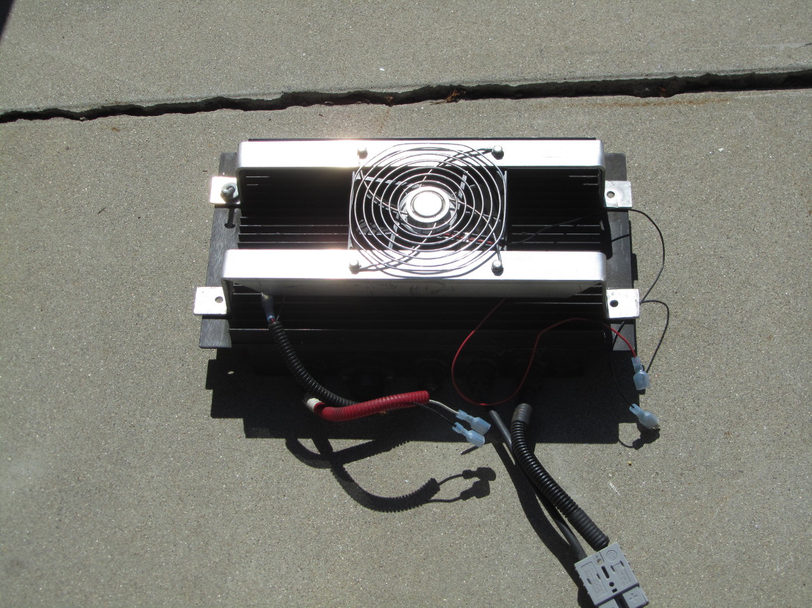
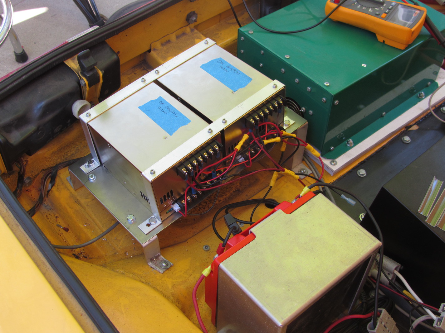
DC-DC Converter upgrade
The old DC-DC converter was only producing 12.5v – not adequate for a normal charging system. After asking around, I ended up buying 2 Meanwell PSP-600-13.5 converters. These are great little boxes, in that they are designed to work in parallel. This also means that with two boxes, I now have 1200 watts of power to drive whatever I want – such as a new stereo.
Charger needs maintenance now
Hmmm, so I got the new 12v battery installed with no trouble. Plugged it in, and it is now fully charged.
Time to charge the main pack. I plug in the pack, turn on the charger, and now it is making an odd hissing noise. I’ve contacted the factory to see what they want me to do. Meanwhile, the car is not a daily driver at all. *sigh*
New 12v Battery
Well, the old 12v gel battery has finally died. I tried a whole day charging it, but nope, wasn’t taking in current. So I ordered and received a new Odyssey PC925 battery. I’ll get it charging up today, and should be able to install it tomorrow.
Of course, I still have issues with either a few batteries being soft or some BMS boards being bad. Not sure which. I’ll try to determine tomorrow. Turns out there is a new version of the miniBMS that has a 30 minute memory of good/bad/over/under. Would be nice to get, but then I’d have to spend another $1500 to do that. If it turns out that I do have some bad BMS boards, I’ll re-evaluate the whole BMS market.
Cold Batteries
Living in San Diego I didn’t expect to have to deal with cold batteries. Turns out the CALBs do not like getting under 45F – they really can’t produce the current I need to drive the car – setting off the miniBMS alarm.
I’m working with a machinist to come up with some insulation for the rear pack, and adding some heating to the packs. Simplest solution is to use plant seedling mats – they heat up whenever the temp drops below 74F. However, I couldn’t use mats due to the criss-cross of support beams. Solution: use soil heating cable. The cable I bought has a built-in thermostat and can cover up to 10 square feet. So now, all I’ll have to do is plug in the car each night – something I already do. 🙂
So when you design your pack, make sure you add in the heating lines for cold weather, as well as the necessary insulation.
Balancing the Batteries
I was able to replace the failed battery without trouble, however, due to that misbehaving battery, the rest of the batteries were no longer in sync – meaning some had a lot more charge than others. I tried bringing the new battery down to the rest of the pack level using a 0.4 ohm resistor (50 feet of 16 gauge wire) – doing this for 5 minutes at a time. It came close, but when charging, the rear half of the pack reached top charge before the top half.
So, after some consultation with battery experts at work, I realized that if I did a REALLY slow charge (2.3A at 110v), then the resistors on the BMS would be able to discharge as fast as I was charging, thus allowing ALL cells to reach that same point. Please note that I have 108 cells, so I had to do some math. 2.3A * 110v = 253W. 108*3.4 = 367v. 253W / 367v = 0.69A. So I’m pushing 0.69A through the pack…ok, resistors can handle that… V = I*R, or I = V / R. Resistor on the BMS is 4.7 ohm. 3.4 / 4.7 = 0.723A. Easy. 🙂
Bad Battery
The BMS was complaining about a battery for some time now, but when it got to the point where the complaint was EVERY morning, it was time to find out which one was bad. This is difficult when there are 108 of them. However, there is a method to finding the bad one:
- Drive a few miles to drop all the batteries to normal operational voltage (3.33 for LiFePO4)
- Expose all the batteries so you can see the BMS chips
- Measure the voltage at all batteries (mark the ones that are low)
- Start charging.
- Mark the batteries that go into shunt mode first
- When charging is done unplug the charger and measure all the batteries.
- Wait 1 hour for batteries to settle and again measure voltage.
Quite likely you will have identified the bad battery in step 3, but steps 5 and 6 will clearly confirm this.
What makes a battery go bad? If the battery is new, then it will fail within a month or less. If the battery has been in the pack for a while, then it has received some form of trauma (such as a connector flopping on and off or been hit or something like that).
In my case, the battery had a loose connector, which caused one of the bars to bounce on and off the battery. This is a Bad Thing ™. To see why, check out this photo:

New Foot Pedal
Well, the old potbox was severely misbehaving, so I replaced it with a Curtis FP-6. Very solid, very nice. Well, it’s kinda big. But solid.
So, I pulled out the old gas pedal, and tried placing it on the floor. It sorta worked, but quite awkward to use. So I took out the old floorboard behind the gas pedal, made a new one I could mount the pedal to, and it is now quite usable. Especially when the carpet covers the wire and box.
Here’s what it looks like:

Gas Gauge Working
It took a while, but I now have an embedded computer listening to the current going in and out of the battery. It is able to calculate the state of charge (SOC) of the pack, and display that value on a LCD screen. Simple enough, right? Just took time and shaking rust off some very old skills (wire-wrapping and soldering). In order to save the life of the auxillary battery, I have two power sources going into the computer. The battery directly powers the computer, and the keyed +12v drives the display. I’ll get some photos up later.