Not controller failure after all

The controller is still working – the problem was in the potbox.  Apparently, the cheaper potboxes can have the rheostat inside slip.  Who knew?

I’ve replaced the old potbox with an all-in-one pedal and potbox from Curtis.  Nice solid construction, but I’ll need to work on the position of the box – the cable from the box is currently under my foot – not good.

Controller Failure

Well, I had to get the car towed home yesterday.  Symptoms:  gradual decrease in power until the motor was no longer spinning.  Fortunately, I was in the right-hand lane of the freeway and was able to pull off on an offramp.

Lessons learned:

1) Check the batteries of your test equipment on a regular basis.  My portable voltmeter’s battery was dead.

2) Keep your towing service – you never know when your car is gonna stop working.  AAA was excellent and only took 15 minutes to arrive.

I REALLY hope the controller isn’t dead, as I didn’t want to buy a different controller just yet.  At least I’ve got a lead on a (hopefully) more reliable one.  Nothing solid yet.

New motor uses less power

Neat.  I calculated the power / mile, and got 290 Wh/mile.  That’s less than with the smaller motor (about 300Wh/mile).  Plus, there is no regen, so *IF* I can ever get that to work with this new motor, the power usage will be even better.

Lesson learned:  larger motors can be more efficient than smaller ones.

Noise, noise everywhere, but no data to be had

Well, I tried two different CANBus sniffers, and there was too much noise on the line for either to work.  I’m going to see if I can isolate the noise (one guess:  the controller), but still not holding out much hope.

On the good news:  I’m in touch with Paul of http://www.paulandsabrinasevstuff.com fame.  They have a beta AC controller designed, and I think I will give it a shot.  Certainly better than nothing.

Update and some Pictures

Ok, car seems to be running ok now.  I have a loose battery connection somewhere that I need to tighten, so that will be my task for the next few nights.

Got the embeded computer installed, and of course, the data coming from the motor is nonsense.  Speed is reported from 0 (although it says 768 at rest) up to 55k RPM.  Temp ranges from 16 to 32K.  So it is obvious that the serial comm is not up to the task.

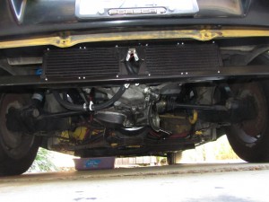
Since there was a request for a picture of the radiators, here is a picture:


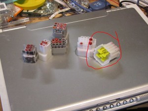
Also a picture of the lousy connectors that I had to replace:

The connector that is circled was smashed during shipment, and the others had wires that would just pop out.

Update on the motor

Ok, so I got the cooling working – had to reseat the pump, as the o-ring has come loose somehow.

So I still have problems with the controller.  However, no way to know what is up without the RS232 hookup.  Well, I spent about 5 hours on Sunday getting the comm to work.  Sort of.  First off, the wires out of the controller are backwards.  Secondly, the controller itself keeps getting confused.

Example:  turn on the controller, listen to the RS232, status is ok.  Spin the motor a bit, and the motor thinks it is in overtemp.  Spin it again, and the overtemp goes away.

Example:  motor speed is a 16-bit value. This value NEVER goes below 762.

Example:  voltage is a 16-bit value. This value ranges from 700 to 20,000.  Never stable.

Next stop is CANBus to see if that is any better.

So far, this controller is rating a C (or maybe C-).  Or for those of the digital persuasion:  4/10.

Oh – and still haven’t gotten regen to work – no clue why not.
Motor works!

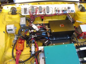
So I was right – it was the cracked/cheap/broken connectors to the motor controller.  I replaced all of the connectors on the controller, and the motor now works VERY well.  I really can’t use first gear anymore.

However, I discovered that I mounted the water pump in a bad position.  According to some sites, I’m not supposed to put the inlet of the pump in a vertical position.  Will keep you appraised of that.

Meanwhile, the new motor is just awesome.  Once I get more comfortable with it, I just might burn rubber.  O_O

Cheers!

More progress

Ok, so the cooling system is all in place now – no leaks.  I’ve got the pump hooked up to run whenever the key is on.  Makes a small gurgle noise, so there is still some air in the system.

Hints:  when installing new hoses, stretch the new hose where it will go over the barbs – makes life a LOT easier for the installer.  Also, make sure the fittings are snug – otherwise, while the hose might be water-tight, the fitting could leak.

I was hoping to bring the car off the jackstands this weekend, but with the rain coming through, it is not very likely.  Really don’t want to mix rain and electrical parts – especially since I haven’t re-installed the rear trunk lid.

I’ll post a picture of the radiators later.

Progress on Motor Adaptor!

Ok, the adaptor is complete, and ready to install.  We’ve made a few attempts to put it in, but had a problem with the spacing around the clutch.  This has been resolved by allowing the pressure plate to move back 0.2″.  During the wait, I’ve rewired the relays, added in a pump and resevoir, and a third brake light.  Hope to have the motor and transmission installed on Sunday.

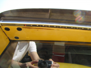
The brake light is a strip of weatherproof side-facing LEDs from www.superbrightleds.com. The wires are hidden behind the chrome.

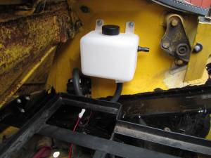
Since both the motor and the controller use liquid cooling, I had to add in a pump and reservoir.  I’ll be running coolant lines from the pump to the controller to the motor to the radiators and back.


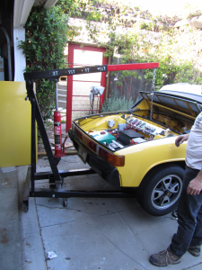
Hoist for the motor and transmission.

The new motor is heavy – 98kg! (216lb). So we have to use this hoist to get the motor and transmission into the car.


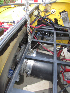
Motor hanging on a chain

The new motor is significantly larger than the old one.  The gap between the new motor and the battery rack is about 6mm (1/4″).


Still waiting for the adaptor

I was told 3 weeks for a new adaptor, and its only been 2 weeks.  I must be getting impatient.  Meantime, I’ve updated my wiring diagram, and will start the rewiring this weekend (subject to the usual interruptions).

I’m also trying to find some software so I can talk to the motor controller, but that’s a very difficult proposition.

Do NOT use permanent loctite

As a public service, I hereby proclaim:

DO NOT USE PERMANENT LOCTITE!

At some point in the future, you will need to dismantle your machine, and using permanent loctite will make this a very painful experience.

Use blue loctite instead.

(This was discovered as we were trying to dismantle the old motor adaptor).

Motor Adaptor Update

Well, I’m going to use a different machinist to create the motor adaptor.  It’s going to be a big project, as the current motor is only 9″ in diameter and the new motor is about 13.5″ in diameter.  So we have to move the rear battery pack up 1.5″, and create a new motor mount for the motor – so it will be a squeeze fitting it in.

Plus, we have to mill a brand new motor adaptor – this will mate the motor to the transmission.  This adaptor has to be precisely a certain length in order for the clutch to work properly.

Work starts on monday.  Will keep you posted on the progress.

Giving up on Automated CNC

Well, my mechanic informed me that the shops that would do computer-controlled CNC are backed up for 2 to 4 months.  So he’s going to do it the old fashioned way – milling machines and measuring.  This is, of course, for the new motor adaptor for the new motor.  Hey – with luck I’ll be driving the new motor by New Years.  🙂

Nothing much right now

When the heat strikes I do to.  Once the temp goes above 90, I have difficult leaving the house.   This is partly due to living in Santa Cruz for so many years, and personal preference.

Anyways, I got the front wheel bearings tightened up today – they were wobbling a bit and I didn’t know why.  After the mechanic stopped laughing at me, it took all of 20 minutes to do.  I’m really hoping to start replacing the battery interconnects soon – I want them done before the new motor mount shows up (is taking a while to get a 3d model built up – more money would speed things for sure).

Finally spun the new motor

Wow.  Took a while, but with a new job, spare time is hard to come by.  At least I won’t be travelling for business (yay!).

Turns out that I had to enable the forward pin by applying +12v.  The contactor line-out is also a ground source (so I had to have the contactor supply +12 to the line).  Interesting method, not what I’m used to, so it was a surprise.

I’m going to update the diagrams and will post them, just in case someone wants them.

YAY!

Older Car Blues

I just got the car back from the mechanic. I had a problem with intermittent electrical issues (the 12v system, not the electric drive). For some reason, brake lights and turn signals were getting confused and not working.  Turns out it was a the ground connection for the main wiring harness being rusty and not connecting properly.

My advice to you: convert the latest car you can.

A coworker’s advice: convert the largest car you can (she has a Kewet – tiny little thing).  🙂

Why build when you can buy?

There are times when it is faster *and* cheaper to buy parts.  Good examples are the motor, controller and stuff like that.  Another example is battery interconnects.  I had earlier posted that I need to have flexible battery interconnects, and that I was going to build them.  Well, my mechanical skills are not so good, and the resulting interconnects are not very good.

So, I ended up buying most of them.  From Australia.  I have trouble believing that you cannot find these parts in North America….but I can’t find them here.

http://www.evworks.com.au/index.php?product=BAT-EVW-BCI-80-8

Good people at Evworks, I’ve bought from them before.