Google Translate is My New Friend

Wow.  I was going through the email that my friend in Shenzen was forward to me with some translation, and I FINALLY realized that I could also translate using Google.  Well.  Color me surprised.  Yes, it was literally translated properly, but no, it wasn’t correctly translated.  So, I’m trying to use Google Translate to do both english and chinese to the factory to make sure I’ve got it all correct with the controller.

For those following the saga at home, the 16-pin connector has a bunch of extra lines out.  Those lines out (9-15) are options that can be programmed at the factory – meaning they do nothing for me.  Now I just need to figure out how the potbox connects and whether I really need -12 and +12 or just +12 and ground.  Details, details. 🙂
Bitterly Drinking a Large Cup of “I Told You So”

Well, remember the nice solid copper battery interconnects I hand-made?  And how some people said I needed to use braided cable?  Well, after doing Yet More Research, they were right.  The problem is that batteries move – all the time – even if you have them strapped.  Mine aren’t strapped.  So if batteries move, and the interconnects don’t, the batteries eventually get damaged.

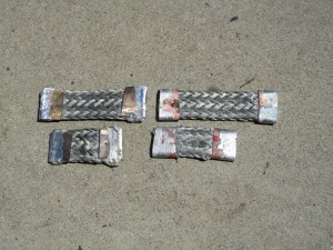
So, in an effort to build some new ones, I tried two techniques:  wrapping copper plate around the cable, and crimping copper pipe to the cable.  As you can see from picture, the pipe does a lot better job.  The pipe crimps nicely to the cable, and doesn’t leave much sticking up (unlike the plate).

So – only 106 more connectors to build.

Copper plate on left side, copper pipe on right side

Old Cars Suck Sometimes

My wife pointed out that the brake lights are very dim on the 914, and I had to agree.  Since I’m using LED light bulbs, this shouldn’t be happening.   It’s odd, though, the bulbs have between 11 and 15 LEDs but only the center LED is on.  I checked the voltage, and it seems ok (13.2 volts), so it must be a current limitation somewhere in the system.

Apparently, the 914s have a weakness in their electrical system at the fuse box inside the main cabin.  The wires get old and break, or the connectors lose their grip, or the wires get crushed by the fuse box and the insulation starts to go.  Or all the above.  Sparky is going back to the shop to see about fixing this very, very soon.

Crouching Rubber, Hidden Rust

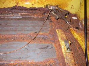
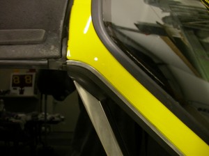
I finally got tired of the rain pouring through the roof (even with the targa top on) and got Sean to replace all the rubber seals in the roof.  Naturally, he had to take the seats out to do this, as it requires clambering about inside the small cabin.  Of course, when he did this, he checked for rust (this is something you should always do with an older car, especially one without rust protection).  Of course, he found rust.

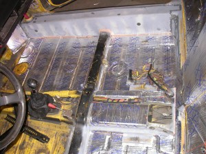
Of course, he fixed it.  AND added in a frame stiffener (914s are a bit weak along the cabin frame).  VERY nice work.

Rust under the driver seat.
Frame stiffener and insulation.
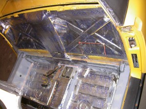
More padding/insulation. Notice - no rust!
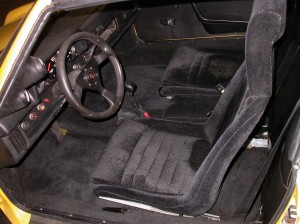
Cabin re-carpeted. No sign of Sean's work.
New rubber seals - apparently a major pain to do.


Inside the Controller

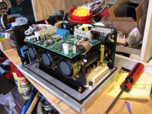
I finally got some spare time and opened up the controller to see what I could see.
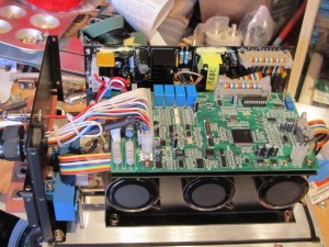
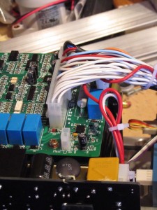
I have a clearer understanding of what most of the lines do – but still do not know where to hook up the accelerator pedal lines. There are 6 lines called “Function” that lead to KB5, KB6, KB7, KB8 and two unmarked inputs on the controller. Not much help there.
I also have a rough idea about the serial lines – three lines that are labeled “gorge line transmit, receive and place” which are hooked to T2OUT, R2IN and one unlabeled wire.

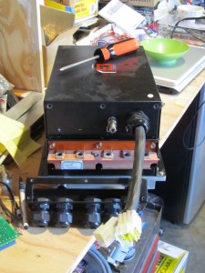
Front of the Controller
Wires from Front to Main Board
Rear of Controller


Delays in research

Sorry about the delays – had a week-long face-to-face meeting, compleate with a BBQ at my house and a dinner at a local restaurant. Busy busy busy. I really hope to have time this weekend for reviewing the motor.

Kick Gas Club

After helping set up a plant sale at Balboa Park, my wife and I made a stop at the Kick Gas Club.  Neat little shop set up by a retired mechanic that specializes in helping people convert their car to electric drive.  The purpose was to see if they could help me with the motor adaptor (which they can’t right now), but they did give me some good ideas on how to proceed.

(BTW – if you are going to get a brand new motor – see if someone else has used it first and get their feedback before putting money into it).

The club can be found here:  http://kick-gas-club-electric-conversions.com/index.html

Charger isolation

Over the weekend I added some isolation to the charger and removed the ground connections, so the charger is completely floating now (relative to ground). This was done by putting some ABS plastic under the charger, and trimming off the ground wires that attach to the charger.

I also replaced the BMS master board, as the feedback from the charger might have damaged it. Not sure what did damage the BMS, but it is working now.  I also had to turn the voltage down on the charger a bit – I suspect the voltage adjust knob is moving on its own.

Showing off at Earth Day

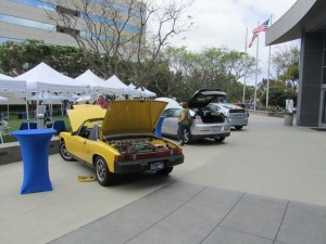
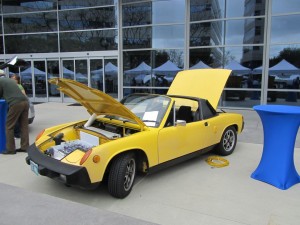
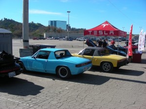
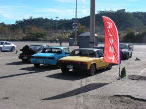
At the Qualcomm Earth Day celebration, I was able to show off my car – alongside 2 Teslas, a Leaf, a Volt, a plug-in Prius, and a Kewet.  Got a LOT of interest in the car – I had printed out 30 handouts, and quickly ran out. I should have printed at least 100!

New motor has finally arrived!

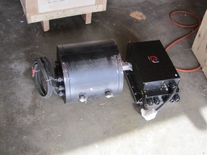
Well, it took a while, but the motor has finally arrived. Spent 2 weeks in US Customs, and another 3.5 days for delivery here, but it is sitting in my garage and smirking at me.
Stats: 11.5″ diameter, 11″ length, 40mm shaft diameter.

New motor from Shengen Motors.

New Motor Ordered

Well, I got tired of trucks passing me on the freeway (I *do* live in San Diego, and people drive very, um, aggressively here). While the car does go 70+ mph, it does not have a lot of acceleration left at that point.

So, I have ordered an 80kw BLDC motor from www.currentevtech.com. Dave says it will take from 3 to 6 weeks for delivery. Meantime, I am looking into new motor mounts, contactors, fuses and such.

The new motor weighs 98kg, and produces 250nm torque. In US units, that motor weighs 216 pounds and produces 107 Horsepower, and 184 ft-pounds.

New BMS installed and working

The new BMS (minibms from Clean Auto LLC) was actually easy to install and understand.  Only one minor complaint – the high-voltage alarm turns on if one of the cells triggers an alert – can be annoying to my neighbor as the car is parked next to his bedroom.  I’ll add a relay to cut off the audible alarm.

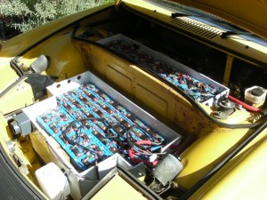
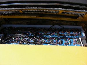
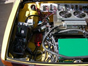
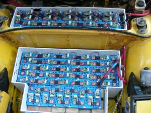
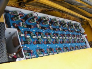
So picture time.  Here are the before pictures.

Front Trunk with old BMS
Rear pack with old BMS

Rear pack with old BMS

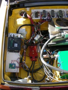
Rear trunk with the old BMS and wiring

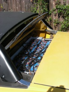
And here are the after pictures.  Much nicer, no?

Front batteries with new BMS
Rear pack with new BMS
New BMS in rear trunk
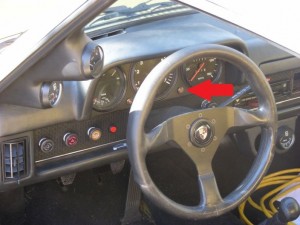
Battery Low/Fault light

The light is a repurposed CAT warning light – I’ll be adding a label to it later. Note that there is also a high-low tone buzzer just under the dash.

Looking into BMS

Well, for my system, there aren’t a lot of choices.  Do a google search for “Lithium Battery Monitor” and you’ll find about 3 vendors.  Since I can’t seem to get Elithion to work, I’m going with the MiniBMS from CleanPowerAuto.  While it doesn’t give me all the stats that Elithion does, I very rarely look at them.  I note that Electric Blue also has a system now that will give that sort of info, but at $15/battery, that is very pricey for me.

I’m still looking into how to display the SOC (State Of Charge) of the system, and so far, I’m quite impressed with Electric Blue’s system – especially so since I can alter the programming.  Will keep you posted on what I choose for the display.

Cheers!

BMS still mis-behaving

I am really annoyed at the BMS (Battery Monitoring System to non-EV people).  I have followed ALL of the directions from Elithion, and it STILL has communication faults and STILL cannot keep the SOC (state of charge) figured out.

Time for a different system.  I can no longer recommend Elithion as a BMS.  It could be because my car is running at 370v, or it could be because of the huge pack of batteries in the back (around 50).  Whatever the reason, it won’t work with my car.  I’m not going to waste any more money on shielding or wire for this.

Argh.

Crimper and Ammeters

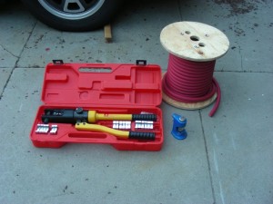
As promised, a picture of the crimper (got it from KTA). WONDERFUL tool.  I wish I had it when I started.

Wonderful Crimper

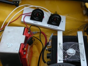
I also installed two ammeters – one for the battery and one for the DC-DC converter. This shows me that both are working as promised, so my right-turn indicator problem is due to the older car wiring.

Battery and DC-DC Ammeters

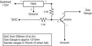
I’ve been busy – this is a circuit that will drive the porsche 914 gas gauge from a 0-5v signal (from the BMS).  I spent a few hours getting the resistors dialed in, but it works on the breadboard – now I just need to solder up a circuit board to do the same thing.

Circuit to drive Gas Gauge

New Cables Installed

Ok, sorry for the delay.  Over Thanksgiving weekend, with the aid of my brother-in-law, the new cables were installed.  MUCH better on the ground fault problem.  I also got to move the power cables to the right-side of the car – away from the communication cables.

So I found a VERY cheap way to solve the GFCI tripping problem – a $0.25 “cheater” plug.  Yeah, it’s not elegant, but it solves the problem of the charger tripping the GFCI all the time.  I’ll keep looking into why the charger behaves the way it does.

I’ll post pix later of the new cables and the new crimper.

Replacement Power Cables

I’ve just ordered new power cables.  The kit from EA provided 2 gauge cables – those are undersized for this project (big surprise there).  I’m ordering 2/0 gauge cables from www.polarwire.com.  They have cables that are suitable for vehicles up in Alaska – should do just fine in San Diego.  🙂

Ground Fault with Battery Pack

Well, I can’t say I wasn’t warned.  The Azure Dynamics controller was complaining quite a bit about a ground fault, and *some* GFCI outlets kept tripping.  I guess I was willfully ignoring the problem.

The problem was brought to the foreground, as the home outlet decide to start complaining when I was charging at 6A.  Not a good thing, and I didn’t want to start charging on non-GFCI outlets.

I consulted with a friend at work that just happens to know power supplies VERY well, and has a personal scope.  I brought the car over, and we looked at the power going in and out of the charger.  LOTS of noise on the ground line – on the order of 0.5A peak-to-peak at 50khz.  Enough to trip a normal GFCI.  Ok, so it is time to isolate the problem.

The kind people on the EVDL list (www.evdl.org) brought my attention to ground faults in the pack.  Following this lead, I did some careful measurements and discovered that the high-power DC lines from the pack are leaking voltage to the car body.  *sigh*

So, assuming that the cables are indeed the culprit, I need to replace them with something that can withstand 370v DC and 200A.  Yup, gonna be fun.

At the very least, I get to move the power lines to different tubes from the control cables.