Battery heating

Something I now have to consider is how to keep the batteries warm in wintertime.  Fortunately, I don’t have to worry about snow or ice, but it does get close to freezing. So when I redo the pack, I will install battery warming pads – these will be plugged in when the car is plugged in – they have built-in thermostats, so it is set-and-forget.

Example:  https://www.amazon.com/dp/B000I8VL16/ref=wl_it_dp_o_pC_nS_ttl?_encoding=UTF8&colid=ECZS9XXRJF00&coliid=I1DAV5PWDDSP7T

That and some insulation around the side should help tremendously.

Pack considerations

I was chatting with a friend who also has a home-made EV about my pack issues.  She also uses CALB batteries, but went with the CALB100AH (blue) instead of the CALB60AH. She’s in the process of parting out the EV, so I get her batteries.

This means I will rebuild the pack using CALB100AH – lower voltage but much better current.  I now need to figure out how many I can fit into my existing space.

She had another suggestion:  take the good CALB60AH and double it – turning two 60AH batteries into one 120AH battery. I’m going to play with that idea and see how well it all works out.

On the bad news front, CleanPower has sold their business, so I’m not sure if I can get more of the MiniBMS.  I’ll just have to be careful with what I have for now.

Battery pack requirements

So, so more thoughts on the new pack.  I don’t want to have liquid cooling – I’ve already got enough problems with cooling the motor and controller. This takes out the Tesla batteries as well as the Volt/Bolt batteries.  Also, it just doesn’t get as hot in Santa Cruz as it does in San Diego.

However, it does get cold – we’ve had near freezing weather for the last few weeks, and that is not good for driveability (or for the number of amps you can draw).

So I’ll have to heat the pack somehow – this will be built into the pack from the start this time. My thought is to use some kind of ceramic heating pad (gardening shop here I come) under the batteries.

I also want a full-fledged BMS this time as well – the miniBMS did what it promised (tell me when something is wrong but nothing else) – but that isn’t good enough. I need to know which cell is failing, and to be able to do trending on the cells’ capabilities.

Research continues!

Time for new batteries

The pack is about 8 years old, and was subject to a lot of hot weather (over 100F/38C). Several cells have gone bad, and it is not possible to buy the blue CALB 60AH batteries any more.

I’m investigating different technologies – CALB, Leaf, and Volt. Tesla would be lovely, but I’m not a rich guy. 🙂

New 12v Battery

Well, the old 12v gel battery has finally died.  I tried a whole day charging it, but nope, wasn’t taking in current.  So I ordered and received a new Odyssey PC925 battery.  I’ll get it charging up today, and should be able to install it tomorrow.

Of course, I still have issues with either a few batteries being soft or some BMS boards being bad.  Not sure which.  I’ll try to determine tomorrow.  Turns out there is a new version of the miniBMS that has a 30 minute memory of good/bad/over/under.  Would be nice to get, but then I’d have to spend another $1500 to do that.  If it turns out that I do have some bad BMS boards, I’ll re-evaluate the whole BMS market.

Cold Batteries

Living in San Diego I didn’t expect to have to deal with cold batteries.  Turns out the CALBs do not like getting under 45F – they really can’t produce the current I need to drive the car – setting off the miniBMS alarm.

I’m working with a machinist to come up with some insulation for the rear pack, and adding some heating to the packs.  Simplest solution is to use plant seedling mats – they heat up whenever the temp drops below 74F.  However, I couldn’t use mats due to the criss-cross of support beams.  Solution:  use soil heating cable.  The cable I bought has a built-in thermostat and can cover up to 10 square feet.  So now, all I’ll have to do is plug in the car each night – something I already do.  🙂

So when you design your pack, make sure you add in the heating lines for cold weather, as well as the necessary insulation.

Giving up on Automated CNC

Well, my mechanic informed me that the shops that would do computer-controlled CNC are backed up for 2 to 4 months.  So he’s going to do it the old fashioned way – milling machines and measuring.  This is, of course, for the new motor adaptor for the new motor.  Hey – with luck I’ll be driving the new motor by New Years.  🙂

Bitterly Drinking a Large Cup of “I Told You So”

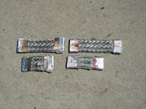
Well, remember the nice solid copper battery interconnects I hand-made?  And how some people said I needed to use braided cable?  Well, after doing Yet More Research, they were right.  The problem is that batteries move – all the time – even if you have them strapped.  Mine aren’t strapped.  So if batteries move, and the interconnects don’t, the batteries eventually get damaged.

So, in an effort to build some new ones, I tried two techniques:  wrapping copper plate around the cable, and crimping copper pipe to the cable.  As you can see from picture, the pipe does a lot better job.  The pipe crimps nicely to the cable, and doesn’t leave much sticking up (unlike the plate).

So – only 106 more connectors to build.

Copper plate on left side, copper pipe on right side

Inside the Controller

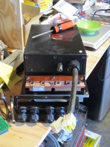
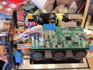
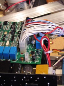
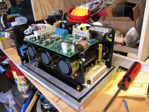
I finally got some spare time and opened up the controller to see what I could see.
I have a clearer understanding of what most of the lines do – but still do not know where to hook up the accelerator pedal lines. There are 6 lines called “Function” that lead to KB5, KB6, KB7, KB8 and two unmarked inputs on the controller. Not much help there.
I also have a rough idea about the serial lines – three lines that are labeled “gorge line transmit, receive and place” which are hooked to T2OUT, R2IN and one unlabeled wire.

Front of the Controller
Wires from Front to Main Board
Rear of Controller


Kick Gas Club

After helping set up a plant sale at Balboa Park, my wife and I made a stop at the Kick Gas Club.  Neat little shop set up by a retired mechanic that specializes in helping people convert their car to electric drive.  The purpose was to see if they could help me with the motor adaptor (which they can’t right now), but they did give me some good ideas on how to proceed.

(BTW – if you are going to get a brand new motor – see if someone else has used it first and get their feedback before putting money into it).

The club can be found here:  http://kick-gas-club-electric-conversions.com/index.html

Looking into BMS

Well, for my system, there aren’t a lot of choices.  Do a google search for “Lithium Battery Monitor” and you’ll find about 3 vendors.  Since I can’t seem to get Elithion to work, I’m going with the MiniBMS from CleanPowerAuto.  While it doesn’t give me all the stats that Elithion does, I very rarely look at them.  I note that Electric Blue also has a system now that will give that sort of info, but at $15/battery, that is very pricey for me.

I’m still looking into how to display the SOC (State Of Charge) of the system, and so far, I’m quite impressed with Electric Blue’s system – especially so since I can alter the programming.  Will keep you posted on what I choose for the display.

Cheers!

Crimper and Ammeters

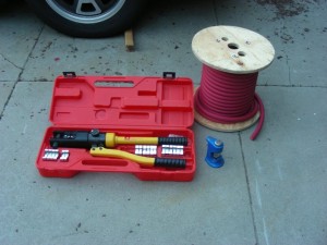
As promised, a picture of the crimper (got it from KTA). WONDERFUL tool.  I wish I had it when I started.

Wonderful Crimper

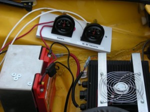
I also installed two ammeters – one for the battery and one for the DC-DC converter. This shows me that both are working as promised, so my right-turn indicator problem is due to the older car wiring.

Battery and DC-DC Ammeters

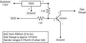
I’ve been busy – this is a circuit that will drive the porsche 914 gas gauge from a 0-5v signal (from the BMS).  I spent a few hours getting the resistors dialed in, but it works on the breadboard – now I just need to solder up a circuit board to do the same thing.

Circuit to drive Gas Gauge

Ground Fault with Battery Pack

Well, I can’t say I wasn’t warned.  The Azure Dynamics controller was complaining quite a bit about a ground fault, and *some* GFCI outlets kept tripping.  I guess I was willfully ignoring the problem.

The problem was brought to the foreground, as the home outlet decide to start complaining when I was charging at 6A.  Not a good thing, and I didn’t want to start charging on non-GFCI outlets.

I consulted with a friend at work that just happens to know power supplies VERY well, and has a personal scope.  I brought the car over, and we looked at the power going in and out of the charger.  LOTS of noise on the ground line – on the order of 0.5A peak-to-peak at 50khz.  Enough to trip a normal GFCI.  Ok, so it is time to isolate the problem.

The kind people on the EVDL list (www.evdl.org) brought my attention to ground faults in the pack.  Following this lead, I did some careful measurements and discovered that the high-power DC lines from the pack are leaking voltage to the car body.  *sigh*

So, assuming that the cables are indeed the culprit, I need to replace them with something that can withstand 370v DC and 200A.  Yup, gonna be fun.

At the very least, I get to move the power lines to different tubes from the control cables.
Computer Control of Power and Fan

I’ve been playing with the Parallax Stamp computer and have come to this conclusion:  it is fun.  🙂

My main process is going to have these steps:

main:

read motor temp

if (temp < 130C) use high power, fan is off

else if (temp < 145C) use medium power, fan is off

else if (temp > 150C) use medium power, fan is on

goto main

This loop will only use 2 relays (one for fan, one for power control).  If I were to use low power setting, I’d need another relay.

I’m hoping to install the computer this weekend, but the weather may delay that (getting REALLY hot here in San Diego).  At the very least, I hope to replace the power supply for the BMS with something much smaller.

Crazy computer idea

I’ve gone and purchased a small embedded computer to read the motor temperature and enable/disable the fan for the motor (www.parallax.com).  Nice stuff, very easy to work with.

However, since I now have this computing capability, why not use it to set the power settings for the controller as well?  The idea is that when the motor is cold, allow more power to flow into the motor, and when it is warm, turn down the power.  Azure Dynamics has 3 power settings available (max, norm, economy), and that is selectable by resistance into a line into the controller.

Hmmm.  This is gonna be fun.  🙂

An old yarn

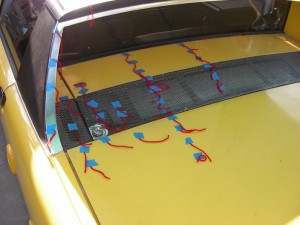
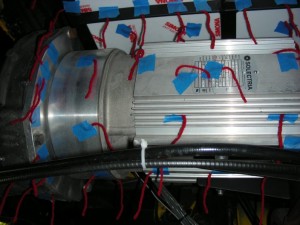
In order to figure out where the airflow is and is not, my mechanic suggested we use a really old technique – tape yarn to the car and see where the wind blows it.  Well, we did that.  We taped a whole bunch of  yarn, courtesy of my charming wife, to the motor, transmission and engine compartment.  Then we video taped the yarn whilst driving.  We discovered that with the big battery box above the motor, there wasn’t very good airflow from the top to the bottom.  Then we removed the rear valence (an air dam just below the rear bumper – used for the now non-existent bumper) and video’d again.  Much better airflow.  So now, I get to replace the air dam in front of the engine compartment with something bigger, and video again.  If this doesn’t improve the airflow, then it will be time for air scoops.

Yarn above the motor

Yarn on the motor

Overtemp

Argh. Now that I’m driving the car more, the bugs are starting to come out. On the drive home today and yesterday, the controller has gone into over-temp protection. I need to figure out what is going on. 🙁