New motor uses less power

Neat.  I calculated the power / mile, and got 290 Wh/mile.  That’s less than with the smaller motor (about 300Wh/mile).  Plus, there is no regen, so *IF* I can ever get that to work with this new motor, the power usage will be even better.

Lesson learned:  larger motors can be more efficient than smaller ones.

Noise, noise everywhere, but no data to be had

Well, I tried two different CANBus sniffers, and there was too much noise on the line for either to work.  I’m going to see if I can isolate the noise (one guess:  the controller), but still not holding out much hope.

On the good news:  I’m in touch with Paul of http://www.paulandsabrinasevstuff.com fame.  They have a beta AC controller designed, and I think I will give it a shot.  Certainly better than nothing.

Update and some Pictures

Ok, car seems to be running ok now.  I have a loose battery connection somewhere that I need to tighten, so that will be my task for the next few nights.

Got the embeded computer installed, and of course, the data coming from the motor is nonsense.  Speed is reported from 0 (although it says 768 at rest) up to 55k RPM.  Temp ranges from 16 to 32K.  So it is obvious that the serial comm is not up to the task.

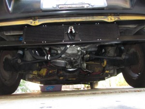
Since there was a request for a picture of the radiators, here is a picture:


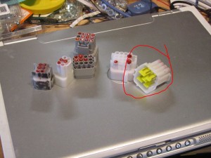
Also a picture of the lousy connectors that I had to replace:

The connector that is circled was smashed during shipment, and the others had wires that would just pop out.

Update on the motor

Ok, so I got the cooling working – had to reseat the pump, as the o-ring has come loose somehow.

So I still have problems with the controller.  However, no way to know what is up without the RS232 hookup.  Well, I spent about 5 hours on Sunday getting the comm to work.  Sort of.  First off, the wires out of the controller are backwards.  Secondly, the controller itself keeps getting confused.

Example:  turn on the controller, listen to the RS232, status is ok.  Spin the motor a bit, and the motor thinks it is in overtemp.  Spin it again, and the overtemp goes away.

Example:  motor speed is a 16-bit value. This value NEVER goes below 762.

Example:  voltage is a 16-bit value. This value ranges from 700 to 20,000.  Never stable.

Next stop is CANBus to see if that is any better.

So far, this controller is rating a C (or maybe C-).  Or for those of the digital persuasion:  4/10.

Oh – and still haven’t gotten regen to work – no clue why not.
Motor works!

So I was right – it was the cracked/cheap/broken connectors to the motor controller.  I replaced all of the connectors on the controller, and the motor now works VERY well.  I really can’t use first gear anymore.

However, I discovered that I mounted the water pump in a bad position.  According to some sites, I’m not supposed to put the inlet of the pump in a vertical position.  Will keep you appraised of that.

Meanwhile, the new motor is just awesome.  Once I get more comfortable with it, I just might burn rubber.  O_O

Cheers!

Finally spun the new motor

Wow.  Took a while, but with a new job, spare time is hard to come by.  At least I won’t be travelling for business (yay!).

Turns out that I had to enable the forward pin by applying +12v.  The contactor line-out is also a ground source (so I had to have the contactor supply +12 to the line).  Interesting method, not what I’m used to, so it was a surprise.

I’m going to update the diagrams and will post them, just in case someone wants them.

YAY!

Ground Fault with Battery Pack

Well, I can’t say I wasn’t warned.  The Azure Dynamics controller was complaining quite a bit about a ground fault, and *some* GFCI outlets kept tripping.  I guess I was willfully ignoring the problem.

The problem was brought to the foreground, as the home outlet decide to start complaining when I was charging at 6A.  Not a good thing, and I didn’t want to start charging on non-GFCI outlets.

I consulted with a friend at work that just happens to know power supplies VERY well, and has a personal scope.  I brought the car over, and we looked at the power going in and out of the charger.  LOTS of noise on the ground line – on the order of 0.5A peak-to-peak at 50khz.  Enough to trip a normal GFCI.  Ok, so it is time to isolate the problem.

The kind people on the EVDL list (www.evdl.org) brought my attention to ground faults in the pack.  Following this lead, I did some careful measurements and discovered that the high-power DC lines from the pack are leaking voltage to the car body.  *sigh*

So, assuming that the cables are indeed the culprit, I need to replace them with something that can withstand 370v DC and 200A.  Yup, gonna be fun.

At the very least, I get to move the power lines to different tubes from the control cables.

Argh! More problems with BMS

While adding EMI shielding to some of the comm wires, I accidentally dropped one of the wires with exposed shielding onto the battery pack.  Nice little spark, but now all but 1 of the banks are not reporting.  *sigh*

So now I’m talking to the Elithion support person to see what I should do next (other than pull my hair out).

Loose Battery Posts

Well, I was warned, and I forgot.  I was reminded again, and lo and behold – there were loose battery posts.  3 of them.

So, I tightened them up, and charged the batteries, and sure enough – the BMS fault during charging is now gone.

Next step is to take Sparky driving and see if the acceleration also causes faults – I sure hope not.

Getting Hot Here

On the drive home, the BMS decided it was a) too hot, b) over voltage, c) under voltage and d) really confused as to the state of charge.  Sparky is hereby grounded until further notice.  🙁

So, what I need to do is figure out the following:

a) why are banks of communication failing during acceleration?

b) why are banks of communication failing during charging (different banks mind you)?

c) why is the BMS not remembering the state of charge?

d) why is the BMS not presenting the correct state of charge via the 0-5v output?

Lots of work ahead for me.

Embedded computer

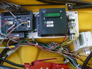
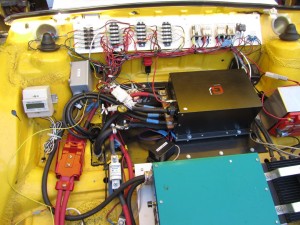
I’ve gotten the computer installed and working.  It does some very simple processing, that (to be honest) should have been handled by the motor controller.

The embedded computer measures the outside temperature of the motor, and then turns the motor fan on or off, and changes the power level of the motor controller.

Simple stuff, really.  I’m sure *someone* could have done it entirely in hardware, but being a computer programmer from years back, this was a better way for me to go.

New Embedded Computer

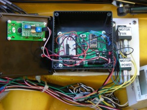
Inside the New Computer

Airscoops and Power Settings – FTW

After getting email from Azure and some really nice folks on the 914 conversion list, I have set the power limit for the motor to 30kw.  I’ve also installed some custom-made airscoops.

Net result:  no overtemp on the drive home.  Yay!  We’ll see how this works out for the summertime, but this means I can drive home now without a long stop somewhere.  (FTW == For The Win, if you aren’t into the geek slang).

Here’s a picture of the custom airscoop:

Custom Air Scoop

Fan doesn’t help

Well, I added a 10 inch fan to cool the motor, and while it did to *some* good, it didn’t do enough.  I’ve sent data to Azure Dynamics to see if they have a clue what’s up.  If I can’t find a way to stop the motor from overheating, I’ll have to find a new motor and controller combo.

Still overheating. :(

On the drive home it went into overheat mode at the 7 mile mark (out of 17 mile drive).  Obviously, the removal of the rear air dam and the addition of the engine compartment air dam did not help.

Next stop – air scoops and fans.

An old yarn

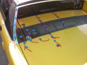
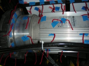
In order to figure out where the airflow is and is not, my mechanic suggested we use a really old technique – tape yarn to the car and see where the wind blows it.  Well, we did that.  We taped a whole bunch of  yarn, courtesy of my charming wife, to the motor, transmission and engine compartment.  Then we video taped the yarn whilst driving.  We discovered that with the big battery box above the motor, there wasn’t very good airflow from the top to the bottom.  Then we removed the rear valence (an air dam just below the rear bumper – used for the now non-existent bumper) and video’d again.  Much better airflow.  So now, I get to replace the air dam in front of the engine compartment with something bigger, and video again.  If this doesn’t improve the airflow, then it will be time for air scoops.

Yarn above the motor

Yarn on the motor

Overheating the Motor

Well, it is the motor that is being overheated.  Not surprising, considering there is a huge battery pack just above the motor, blocking airflow upward.  I’m now looking into how to install a fan or installing some ducting or both.